Compressed Air Driven Motor
Abstract
The target of discussion in this paper is improvement of devices, which translate some kind of energy into motion, such like motors. Nowadays, many different motor types are in use worldwide, such like different models of combustion engine motors, supplied by some kind of explosive fuel, which translate the explosion power under the controlled circumstances into linear oscillations, thus in circular movement, like in the instance of piston engines. The other kind of widely used devices are electrical power supplied motors, which are also presented in numerous models of devices, which all need electrical energy to convert to mechanical motions. In this discussion, it will be represented the way how to implement one 101 years old invention made by the most famous inventor allover the world, the citizen of the world Nikola Tesla, in order to convert the compressed air in closed loop stream along with implementing the energy amplification, to get the fuelless self-sustained motor of high efficiency, which needs to be initialized to start to spinning all the time long, without to spent any additional energy.
Description
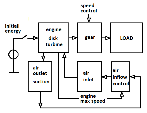
The compressed air supplied motor, which converts an air motion into mechanical rotation, thus store the kinetic energy within the high speed spinning rotor, on which shaft could be coupled some mechanical load, which needs to be supplied with power to fulfill some useful work, was created from the continuum of logical streaming, as the result of brainstorm methodology applied with an aim to improve an old fashion aircraft propeller propulsion, as an example for better explaining the universal self-sustained fractal model. The aim of development was to publish the presentation of universal fractal model of self-sustained properties implemented on several practical examples for educative purposes. The optimization of compressed air turbine application has lead us toward the closed loop application without the propeller. Logically, instead of propeller, which allow for feedback, the air stream has been looped back from the air outlet to the air inlet. The system must not be, but could be pneumatic closed, but rather the air stream has to be properly managed.
In the matter of fact, the disk-stack Tesla's turbine is very efficient, thus it needs only pretty few air pressure to reach the full speed. How high the pressure must be introduced depend on particular case, concerning the properties of the rotor, such like of which weight it is, how many disks are mounted in stack, how wide is the space between them, and how is applied additional energy from environmental surrounding, which in this particularly case concern the air stream vortex accelerator, and how strong is the vacuum suction intensity at the air outlet of the turbine-motor.
The motor needs initial energy to speed up, before the self-sustained mod could be established. This is only an energy impulse which could be introduced in many different ways, depending on the weight of the rotor, and power of the load. The start up energy impulse could be compressed air stream, got from some air compressor or mechanical system for speed up the rotor initially, which could be manual like start wheel with line to be pulled, or electric motor, or the like.
The far the turbine starts to speed up, the air is going to be compressed out of the turbine case, due to the suction system joined at the air outlet, which is then going to be looped back to an air inlet. The turbine could work as both, the motor or the air pump. If we are going to spin the turbine rotating the shaft, the rotor is going to exhaust the air at outlet and to suck it at the inlet, involving additional environmental air using the simple jet nozzle. The faster the rotor spins, the more air is going to be exhaust and the higher amount of the environmental air involved in the system due to suction principal of the jet nozzle is going to speed up additional air mass within the snail airstream accelerator.
While the system is running in closed loop, the rotor is going to speed up very fast until the maximum revolutions per minute. The maximal speed of the rotor could be very fast, such as over 15,000 rpm without the load, thus the rotor must be mounted on the shaft very precisely in order to avoid appearing of the mechanical vibrations, thus appearing of mechanical resonance, and total damage of the system, which could be dangerous. The maximal mechanical power, which could be extrapolated on the shaft, occurs at half of maximal speed, accordingly to the bell shaped resonance curve.
The speed could be generally limited controlling the air flow, or power of the load. Furthermore, the larger diameters, the more sensitive system on vibrations, thus in moving applications it would be advisable to implement smaller disk diameter, to avoid sensitivity on vibrations. On the other hand, the larger diameter of the rotor, its weight and the speed of spinning, the larger kinetic energy stored within, thus the maximal resulted power possible to be extracted of the shaft. Therefore, there is the task to find the best case for particular purpose experimentally.
The gear or power transmission system is designed depends on power amount to be transmitted. The turbine could be designed to match some existing standard power transmission system, which could be similar to this one, which is used to control the speed and power of cars.
The energy amplification build in system is based on involving additional energy from environmental surrounding, in form of kinetic energy stored in swirled air, which enlarges significantly the airstream speed due to producing an air vortex, which in turn would increase an air inflow pressure within the disk turbine. On the other hand, additional air pressure is allowed by implemented suction system joined at the closed loop airstream. The suction system could be a simple jet nozzle, but also the modified vacuum cleaner in role of under-pressure magnifier, such as this one which is used by bag-less vacuum cleaners, like a cyclone, Dyson or similar, with an aim to involve additional air of environment into the turbine. The principle of bounded nozzles is going to be implemented in this case, which would increased the vortexes of an airflow, thus intensify the suction at the turbine inlet, and consequently at the turbine outlet as well. Increasing the suction intensity will cause increasing of an air mass inflow within the turbine, enlarging the pressure of an air inflow thought the inlet nozzles, which in turn is going to increase the speed of the rotor. The suction system could be reused of some appropriate types of vacuum cleaner, as well as developed as simplified model, to match the needs of application. The stronger the suction, the more air mass is going to be introduced within the turbine, providing for the higher translation of energy from the airstream vortex inflow to the spinning of the rotor.
The translation of the airstream inflow to the rotating of the rotor based on friction between the airstream and the surfaces of particular disks in the rotor stack. The mentioned friction based on adhesive forces between the molecules of the air and the material of which the disks consist of, which is in this particularly case preferable stainless steal. The far the rotor starts to spin, the airstream will going to follow the spiral trajectory toward the center of the rotor, where nearby the shaft numerous of outlet opens are drilled through the whole stack of the disks, as well as through one wall of the turbine case. In this way, an inflowing air could be exhausted out of the turbine.
The translation of the airstream inflow to the rotating of the rotor based on friction between the airstream and the surfaces of particular disks in the rotor stack. The mentioned friction based on adhesive forces between the molecules of the air and the material of which the disks consist of, which is in this particularly case preferable stainless steal. The far the rotor starts to spin, the airstream will going to follow the spiral trajectory toward the center of the rotor, where nearby the shaft numerous of outlet opens are drilled through the whole stack of the disks, as well as through one wall of the turbine case. In this way, an inflowing air could be exhausted out of the turbine.

The speed of the airstream is of significant influence on the maximal power of the turbine. Spinning the air up,
the additional kinetic energy is going to be introduced into the system, thus the special attention should be payed to developing the air inlet and outlet subsystems, which both could be very simple. The air inlet consists of the snail shaped tube with gradually decreased diameter along the tube, from the air inflow open toward the nozzle mounted at the turbine case. The snail shape tube is going to support appearing of the air vortexes, speeding up an airstream significantly. Additional air mass could be introduced using the simple jet nozzle.
the additional kinetic energy is going to be introduced into the system, thus the special attention should be payed to developing the air inlet and outlet subsystems, which both could be very simple. The air inlet consists of the snail shaped tube with gradually decreased diameter along the tube, from the air inflow open toward the nozzle mounted at the turbine case. The snail shape tube is going to support appearing of the air vortexes, speeding up an airstream significantly. Additional air mass could be introduced using the simple jet nozzle.

An influence of the suction intensity to an air mass inflowing into the turbine, could be regulated implementing some adjustable valves located in loop-back between the turbine outlet and the air suction system, in order to regulate the rotor speed within the boundaries of certain band with.
Also without to form the loop back bounding the air outlet to the air inlet, the turbine will going to run properly. Introducing the loop back, the additional environmental energy is going to be introduced within the system, so the efficiency of the device could be significantly improved.
Conclusion
This inexpensive device which is very simple but very powerful, could be introduced in large scale. The motors of this kind are scalable between the certain margins, not such like electrical power supplied motors, but their simplicity pull them on the top, along with the most important matter of fact that there is no need for any fuel to drive this kind of motors. This matter of fact could bring the industry the huge support, which is similar to the huge financial injection. Although for producing the useful mechanical power, we would not need to pay for fuel, the appropriate taxes should be implemented which could still be lower then an actual consumption amount. An oil industry should not collapse, thus collected financial goods could be invested in converting certain part of oil industry into another branches, such like recycling for instance.
An aim of inventions, development and doing business is at least not to cause collapse and brake the economy, but rather to improve it.
Although another models of turbines could be implemented, the friction based disk stack turbine invented by Nikola Tesla 101 Years ago in USA, is the best solution, because of extremely high efficiency. Furthermore, the simplicity is also of high importance concerning the mass introduction. Unfortunately there are not sufficient data available concerning the performance of this type of turbine, because of the leak of experience. Therefore, it would be necessary to organize investigation, in many teams, worldwide in order to compare the results. Shearing the results among each others is going to significantly improve for accurate analysis of the results in order to estimate the possibilities for the mass production and faster implementation on the large scale. This would reduce the overall waste, which is a main goal of any optimization. The inventions of common importance are therefore belong to this kind of license.
The government of Yugoslavia has been inherited the licenses rights along with all properties of Sir Tesla after he died. The Tesla's property has been inherited by the government of Serbia, after Yugoslavia has been collapsed.
The far I'm informed about the actual state, all Tesla's patents are free of any license, but this has to be checked. My personal wish is that such an inventions have to be protected of monopolization of any art. This means that any general representatives for the whole world could be in the same way destructive as an exclusive rights on some patents, while it stops development. There are already presented new models of licensing the inventions such as open source license, which is always more and more implemented on better for the whole world, on overall benefits.
There must be found another way how to reward and stimulate the inventors to invent, as well as how to protect them of spying with an aim to still their ideas and to publishing them under own name. This kind of crime must be stopped, since the damages produced in this way are immense. Since the ideas are of havens origin they couldn't be the private properties. Only materialized products could be the private properties. The ideas are to be shared worldwide. What is still missing is the way how to reward the inventors. In the matter of fact, if someone is going to improve his own business thanks to some ideas, normally would be to give some reward to inventor, or even to share the part of profit with him. This happens very often, but could be even more often. The point is that such people regularly do not need to be very rich, but rather to be supported instead of to be disturbed by demolishing of some important resources of life relevance.
The investigation in the case of Tesla turbine could be made by involving the number of independent teams, worldwide and to share the results of investigation among them, to reach the best results. A number of investigations could be finished as the part of final or doctor work at universities.

Appendix
Compressed air driven motor efficiency could be extremely increased just using the airflow in closed loop. It is easy to imagine which result is going to be achieved by simple closing any kind of fan closed within the narrow box with two opens, one for an air inlet and another for an air outlet. Just join one end of the pipe directly to an air outlet of the fan case, and another end of the pipe to an air inlet using the simple jet nozzle. The jet nozzle, which allows for additional air suction to supply the turbine, is very simple. It consists of one tiny air inlet which fits into the slightly brighter pipe, mounted to the turbine box to allow for additional air inflow. The two size pipes mounted within each other, building the air suction jet, since the additional air inflow is going to be introduced into the turbine from surrounding environment through the ring space at junction between two pipes.
While the turbine is going to suck in always more and more air, it is necessary to allow for an air outflow, which has to be adjustable in order to get optimal power transmitted, and to avoid the overpressure to be produced within the turbine, which eventually could provide damages. The speed of the rotor is going to be very fast, thus it is strongly recommended to implement all necessary security measurement to avoid any damage.
Now, we would need only to initialize the fan however we can. To speedup the fan, we could use some additional air inlet joined to an air compressor, to produce an impulse to start the fan spinning. We could also use one of many ways to speedup the fan mechanically, spinning the shaft of the fan, such as manually spinning, spinning the rotor by pooling the line wrapped on wheel, or using some starter motor coupled to the shaft of the fan. In the last case, after short time introduced electrical energy to speedup the motor, after disconnecting it from the energy source, the motor will start to work as generator, which maximal speed has to mach the real speed of the turbine.
The fan is going to spin in self-sustained mode. The air exhausted from the motor is going to be looped back to an inlet, but the air inflow rate is going to be increased along the time. The higher fan speed, the higher air outflow, thus the higher air pressure through an air inlet, which in turns caused higher air inflow rate thanks to the suction jet, which is going to speedup the fan additionally. The fan is going to spin faster and faster, until the load allows for it. The load can be coupled to the shaft directly, or due to using appropriate power transmission system. Some kind of gear could be introduced if we would need to control the load intensity, such like torque and speed.
Although a wide range of turbines could be implemented on this purpose, the best solution represents a Tesla turbine, since it is very simple, small, inexpensive and very efficiently.
One more improvement could be made due to matching the measures of our turbine to the metric system, since one meter is in harmony with Earth's measures. Bearing in mind that our turbine-motor is an oscillator, the best results could be expected using a rotor of quarter, half, three quarter or full meter in diameter. In such cases we are going to match the wavelength of planetary oscillations, thus to get the interface to the Universe. In this way we could achieve a lot of more power and efficiency as it could be expected at the first glance.
Of these reasons, recommended measures of the disk rotor for experimental purposes would be 10” or 25 cm, while the rotor should be of 1” thus 2.5 cm thick . Another recommendation of similar reasons is to keep the ratio of measures based to 10, therefore the difference between diameter and high of the rotor. It has to be proved empirically if there is some difference in efficiency between the height of the rotor of 10th of diameter and the height of the rotor of 20th of diameter of the turbines rotor.
However, it remains to decide how many disks are we going to implement into the stack, and how thick each of them should be. The best distance between disks would be such one, which is recommended from inventor himself in the description of his patent, thus of 40 mils or 0,5 mm of space between the disks mounted on the rotor within the stack. Using a stainless steel sheets of the same thickness as a distance between the disks made of them, we would need 25 disks to fill the range of 1” height stack. Using a stainless steel sheet of 1 mm or 80 mils thickness, we would need 17 disks in a stack to get the same height. In the first case the weight of our rotor is going to amount slightly over 5 kg. In the second case the rotor weight is going to amount a little bit less then 7 kg. If we would need the rotor to be of less weight, we could built it to be of half the height, using 12 disks of 40 mils to get 2.5 kg weight or 12 disks of 80 mils to get less then 3 kg of the rotors weight.
Just bear in mind that the more heavy disk is going to save more kinetic energy by the same rotational speed, thus the higher level of usable power is going to be possible to extract from the shaft of the motor. It is to expect that more heavy rotors are going to rotate not that fast such as in the case of less heavy rotors. However, the kinetic energy of the rotor is directly proportional to the square of rotational speed and to a half of the mass of the rotor. Thus, the more weight, the more power – but the higher speed the much more of power. However, the peak of extracted mechanical power from the shaft of the turbine would be maximum at the half of the maximal rotor speed, which is to be confirmed by the measurement.
Following is to be checked for each size of rotor:
ATTENTION: The high speed motor could be very dangerous if it explodes. Therefore all security measurements have to be implemented in order to avoid any life danger. The case of the turbine has to be made of appropriate material, hard enough to inshore for sufficient security. The closed-loop supplying system will produce additional air pressure within the turbine case, thus appropriate security valves are necessary to be implemented, in order to avoid any injury. The author can not take the responsibility in case of accident.
Compressed air driven motor efficiency could be extremely increased just using the airflow in closed loop. It is easy to imagine which result is going to be achieved by simple closing any kind of fan closed within the narrow box with two opens, one for an air inlet and another for an air outlet. Just join one end of the pipe directly to an air outlet of the fan case, and another end of the pipe to an air inlet using the simple jet nozzle. The jet nozzle, which allows for additional air suction to supply the turbine, is very simple. It consists of one tiny air inlet which fits into the slightly brighter pipe, mounted to the turbine box to allow for additional air inflow. The two size pipes mounted within each other, building the air suction jet, since the additional air inflow is going to be introduced into the turbine from surrounding environment through the ring space at junction between two pipes.
While the turbine is going to suck in always more and more air, it is necessary to allow for an air outflow, which has to be adjustable in order to get optimal power transmitted, and to avoid the overpressure to be produced within the turbine, which eventually could provide damages. The speed of the rotor is going to be very fast, thus it is strongly recommended to implement all necessary security measurement to avoid any damage.
Now, we would need only to initialize the fan however we can. To speedup the fan, we could use some additional air inlet joined to an air compressor, to produce an impulse to start the fan spinning. We could also use one of many ways to speedup the fan mechanically, spinning the shaft of the fan, such as manually spinning, spinning the rotor by pooling the line wrapped on wheel, or using some starter motor coupled to the shaft of the fan. In the last case, after short time introduced electrical energy to speedup the motor, after disconnecting it from the energy source, the motor will start to work as generator, which maximal speed has to mach the real speed of the turbine.
The fan is going to spin in self-sustained mode. The air exhausted from the motor is going to be looped back to an inlet, but the air inflow rate is going to be increased along the time. The higher fan speed, the higher air outflow, thus the higher air pressure through an air inlet, which in turns caused higher air inflow rate thanks to the suction jet, which is going to speedup the fan additionally. The fan is going to spin faster and faster, until the load allows for it. The load can be coupled to the shaft directly, or due to using appropriate power transmission system. Some kind of gear could be introduced if we would need to control the load intensity, such like torque and speed.
Although a wide range of turbines could be implemented on this purpose, the best solution represents a Tesla turbine, since it is very simple, small, inexpensive and very efficiently.
One more improvement could be made due to matching the measures of our turbine to the metric system, since one meter is in harmony with Earth's measures. Bearing in mind that our turbine-motor is an oscillator, the best results could be expected using a rotor of quarter, half, three quarter or full meter in diameter. In such cases we are going to match the wavelength of planetary oscillations, thus to get the interface to the Universe. In this way we could achieve a lot of more power and efficiency as it could be expected at the first glance.
Of these reasons, recommended measures of the disk rotor for experimental purposes would be 10” or 25 cm, while the rotor should be of 1” thus 2.5 cm thick . Another recommendation of similar reasons is to keep the ratio of measures based to 10, therefore the difference between diameter and high of the rotor. It has to be proved empirically if there is some difference in efficiency between the height of the rotor of 10th of diameter and the height of the rotor of 20th of diameter of the turbines rotor.
However, it remains to decide how many disks are we going to implement into the stack, and how thick each of them should be. The best distance between disks would be such one, which is recommended from inventor himself in the description of his patent, thus of 40 mils or 0,5 mm of space between the disks mounted on the rotor within the stack. Using a stainless steel sheets of the same thickness as a distance between the disks made of them, we would need 25 disks to fill the range of 1” height stack. Using a stainless steel sheet of 1 mm or 80 mils thickness, we would need 17 disks in a stack to get the same height. In the first case the weight of our rotor is going to amount slightly over 5 kg. In the second case the rotor weight is going to amount a little bit less then 7 kg. If we would need the rotor to be of less weight, we could built it to be of half the height, using 12 disks of 40 mils to get 2.5 kg weight or 12 disks of 80 mils to get less then 3 kg of the rotors weight.
Just bear in mind that the more heavy disk is going to save more kinetic energy by the same rotational speed, thus the higher level of usable power is going to be possible to extract from the shaft of the motor. It is to expect that more heavy rotors are going to rotate not that fast such as in the case of less heavy rotors. However, the kinetic energy of the rotor is directly proportional to the square of rotational speed and to a half of the mass of the rotor. Thus, the more weight, the more power – but the higher speed the much more of power. However, the peak of extracted mechanical power from the shaft of the turbine would be maximum at the half of the maximal rotor speed, which is to be confirmed by the measurement.
Following is to be checked for each size of rotor:
- maximal speed without load coupled to the shaft in self-sustained closed loop mode
- coupling appropriate load to the shaft, such as electric power generator as for instance the motor of the similar speed and a little bit more powerful as an estimated power of turbine counted as product of multiplication of half the weight and square of angular velocity
- measure an rpms accordingly to the power load of the generator coupled on the shaft of the turbine
- to avoid unnecessary speculation about determining an efficiency of the motor, it would be enough to compare the measurement results of all determined cases in order to learn about the influence of the described differences
- determine an
influence of an adjustable air outflow to the power of the motor
- in addition the influence of the air suction system closed in the air flow closed loop, such as some kind of bag-less vacuum cleaner contributing parts for instance, could be determined
ATTENTION: The high speed motor could be very dangerous if it explodes. Therefore all security measurements have to be implemented in order to avoid any life danger. The case of the turbine has to be made of appropriate material, hard enough to inshore for sufficient security. The closed-loop supplying system will produce additional air pressure within the turbine case, thus appropriate security valves are necessary to be implemented, in order to avoid any injury. The author can not take the responsibility in case of accident.
| motor_pogonjen_vazduhom_v3.pdf |
